

Simple Line Detection using Raspberry Pi camera and OpenCV, Python (for drone applications)
- 2017년 3월 17일
- 7분 분량
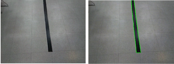
Before and after line detection using OpenCV
In this tutorial, we will explain how to set up a Raspberry Pi with the official camera module in order to perform computer vision tasks using the OpenCV Python library. OpenCV, which stands for Open Computer Vision, is library can be used together with flight controller off-board flight libraries such as DroneKit, or fully manual off-board control using MAVLink in order to implement a wide range of vision-based autonomous drone flight applications. OpenCV is a C++/C library and there are APIs for accessing the library using the Python, Java, and MATLAB programming languages - in this tutorial we will be using the Python programming language. We will look closer at how to detect lines for use in line tracing applications (to make a quad-copter autonomously follow a line that has been painted or marked on the ground).
1. Hardware requirements
- Raspberry Pi (any version)
* The latest revision of of Raspberry Pi - as of writing (March 2017) Raspberry Pi 3 Model B - is strongly recommended as computer vision tasks are very compute-intensive.
- Raspberry Pi Camera Module (V1 or V2)
* Version 2 is recommended for optimal image quality, and it is the version that was used for this tutorial.
Optional:
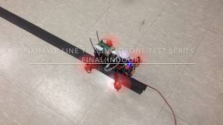
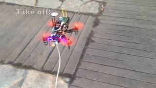
- A quad-copter with a diagonal length of 250mm or longer
* The quad-copter must be large enough to carry the Raspberry Pi with the camera module. In order to control the quad-copter using the Raspberry Pi you will also need a flight controller such as a Pixhawk which can be flashed with ArduCopter firmware that supports off-board control. However, the line detection functions can be tested without a drone. (This tutorial will only cover the computer vision aspect of a drone Line Tracing project, for setting up ArduCopter for off-board control please refer to our other tutorials.)
2. Installing the required software
First and foremost, flash the MicroSD card for you Raspberry Pi with a Pi Linux distribution of your choice, for this tutorial we used Raspbian, as it is the most common distribution and officially supported by the Raspberry Pi Foundation. At time of writing, Raspbian comes with Python 2.7.x installed by default.
Install the required packages by entering the following commands in the terminal application or by accessing the Pi using SSH:
These commands will update your repositories and install the Python OpenCV library, which is the most widely used open source Computer Vision library. At the time of writing the default OpenCV version provided by Raspbian is OpenCV 2.4.x, which is the version we will be using in our tutorial. We also install python-pip which is a package manager for Python packages which we will need to further install the picamera libraries which we will need later. The python-numpy package is required to simplify many mathematical operations which are commonly used in computer vision tasks.
Next, install the Python picamera library using the following terminal command:
This library provides a a pure Python interface to the Pi camera module.
3. Enabling and testing the Pi camera
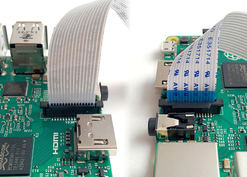
Before we get to writing Python code, we should install and make sure the camera is working properly: first, with the Raspberry Pi switched off, locate the camera port on your Raspberry Pi and connect the camera module:
Next, enter the following command into a terminal:
This command will bring up a configuration menu for your Raspberry Pi, navigate the option 5: Enable Camera and hit <Enter> to enable the camera. Then navigate to Finish and hit <Enter> again to exit the configuration. Finally, you need to reboot the Pi for the settings to take effect.
Next, let's test out the camera: point the camera at some object, and in a terminal enter the following command.
This command will snap a picture and save it in your current directory with the filename test.jpg . You can view it using the Image Viewer application in Raspbian, or by copying it to your local computer over network if you are not accessing your Pi through the graphical interface. If the command produces an error message, make sure you connected your camera cable correctly to the port marked "Camera" and repeat the previous steps.
Check that your test picture is clear and visible, if the picture looks blurry you may need to adjust the focus by rotating the lens using the included circular plastic tool.
4. Getting started with Python and picamera library
If you have installed and checked the camera is working through the instructions in the previous section, you can now get started coding with Python!
For the sake of simplicity, we will assume that you have access to the GUI of the raspberry pi, to display the output image on the screen.
Open up a text-editor of your choice and enter the following lines of code:
Save the file with the name test.py (or a name of your preference). You can execute the python code by entering python test.py in a terminal shell. The camera will snap a picture and display the result in a new window on your screen. You can close the window by pressing any key on your keyboard.
The first lines of the code-snippet above imports the required APIs: picamera, picamera.array, time and cv2 (which is short for OpenCV 2). picamera.array is a sub-module of picamera that enables us to get NumPy arrays from the Pi camera. OpenCV uses NumPy arrays to represent images, so using picamera.array saves us from having to do JPEG encoding and decoding to convert the picamera image into the OpenCV format required for image processing.
Next, we initialize the camera object, set the camera resolution to 640x480 and initialize the rawCapture variable where our image array will be stored. The raspberry pi camera is capable of capturing at resolutions up to 3280x2464, but we recommend using relatively low resolutions because image processing is very compute-intensive. This is especially true when processing images rapidly in real-time. After initializing the camera we wait for 0.1 seconds to give the camera module some time to warm up.
Capturing is done with the picamera.capture() function which takes the capture stream as the first argument and the format as a second optional argument. We use format="bgr" because we want our pictures to be captured in raw BGR format which is the format OpenCV uses for image processing. The cv2.imshow() function displays the image output on the screen and waits for a key input before closing the window and ending the script.
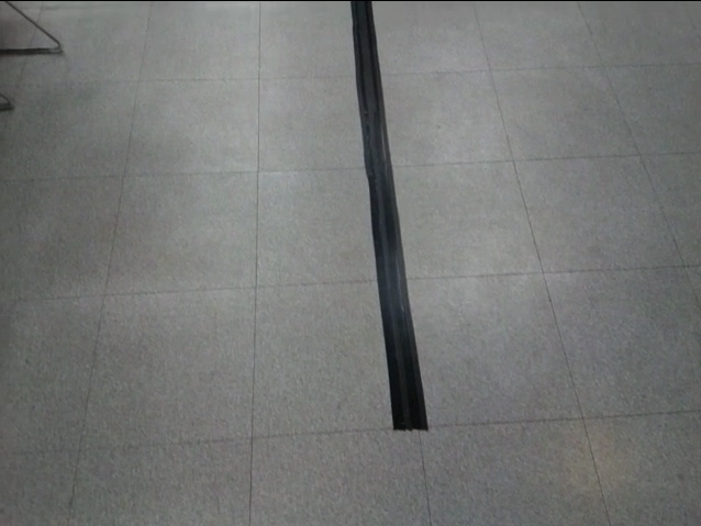
Black line on floor shot with picamera
5. Simple line detection on still images using OpenCV
Now that we have learned how to use the picamera library to capture images in the OpenCV format, let's learn to use OpenCV to do some image processing on the captured still images. Edit the previously created test.py file to include the new lines or create a new python file containing the following lines of code:
We have omitted the import lines at the top of the file for brevity. The basic camera initialization and capture is the same as in the previous section, but we have added code for image processing with cv2.
First, we convert our image to grayscale using the cv2.cvtColor() function, and store it in the gray variable. cvtColor() converts an image from one color space to another, it receives the input image as the first argument and the color space conversion code as the second parameter. The color space conversion code is defined as a constant in the cv2 API, in our case we want to convert from BGR to grayscale hence we use the constant cv2.COLOR_BGR2GRAY. For further reference on conversion codes, and detailed API function definitions please refer to the OpenCV documentation at http://docs.opencv.org/2.4/index.html
All camera sensors have some degree of sensor noise, which can cause the line detection algorithm to erroneously detect the noise as lines or edges in the camera's view. To mitigate the noise we apply Gaussian Blur on the image to blur out the details. We assume that the line in our image is relatively thick and so Gaussian blur will leave the silhouette of the line intact. The cv2.GaussianBlur() function receives the input image as the first argument, the second argument specifies the width and height of the kernel, which should be a positive, odd number. Essentially, a larger kernel size will blur the image more. The third argument to cv2.GaussianBlur specifies the standard deviation in X and Y directions, when given 0 these will be calculated automatically based on kernel size.
With the image noise removed the next line performs Canny edge detection which returns a binary image (image containing only black and white pixels), which we store in the edged variable. The edges of the input image marked with white pixels. The 2 following parameters specify the minVal and the maxVal thresholds for the Canny edge detection, where maxVal should generally be set to 3 times the minVal. Determining the minVal is an advanced topic which is out of scope of this tutorial but for our purposes 50 is a suitable value which works in many lighting conditions.
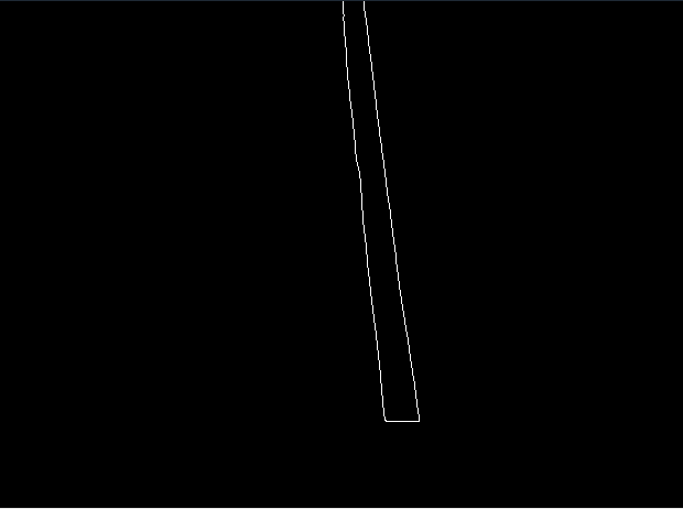
Output of Canny edge detection applied to image shot in previous section
The final step in our image processing pipeline is detecting the straight lines in the image and calculating their start- and ending-points. To do this we use the Hough transform which is a technique for feature extraction which is widely used in computer vision. In our case we the features we are interested in extracting are the lines in our image. It is possible to do that with OpenCV, which has an implementation of Hough lines transform in the cv2.HoughLinesP() function. HoughLinesP returns an array containing the start and end points of the lines detected in the picture. We specify the arguments (edged,1,np.pi/180,10,80,1) - where edged is our binary input image (all input images to Hough transform should be binary). The second and third parameters are distance and angle resolutions for the Hough transform. The fourth parameter "10" given is the accumulator threshold for Hough, this can be decreased or increased to tune the line detection. The fifth argument given, 80, is the minimum line length - lines shorter than 80 pixels will be rejected, this parameter can be tuned to reject short lines that we probably are not interested in. The last argument specifies the maximum gap allowed between lines in the image, for low resolution images like ours the line detection works better when given a value of 0 or 1.
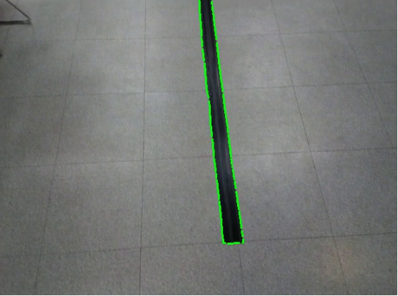
Final line detection overlay result of the line detection script
Lastly, to finish our script and display the result of the image processing on the screen we iterate through the lines array, drawing each line detected by the Hough transform over our original input image to visualize the line(s) detected.


댓글